Designing a replacement for an obsolete Electro Cam control system in a Maac thermoformer using a Teensy Arduino-compatible
A high-output count DIY Arduino industrial controller and interface on the cheap

This story revolves around one of the workhorse machines in the company where I work: a Maac vacuum former. It is a solid, well-designed machine with a solid, well-designed control system that Maac contracted out to the Electro Cam systems group. As with any industrial equipment, as time goes by the OEM develops new products that replace their old stuff, technologies advance, and eventually they start the formal process of obsoleting their older inventory.
The situation started out years ago, long before I arrived on the scene, when the company I work for hired a contractor to add some automation to the Maac. When the automation was added almost all of the Electro Cam system was necessarily replaced with an Allen-Bradley SLC500 PLC to provide the changes in logic & the additional I/O points to do all of the new functions. The only Electro Cam components left in the Maac are the parts in the 84 zone oven controller. This is comprised of:
- CPU & power supply
- Keypad & 7-segment LED display
- Monochrome CRT display
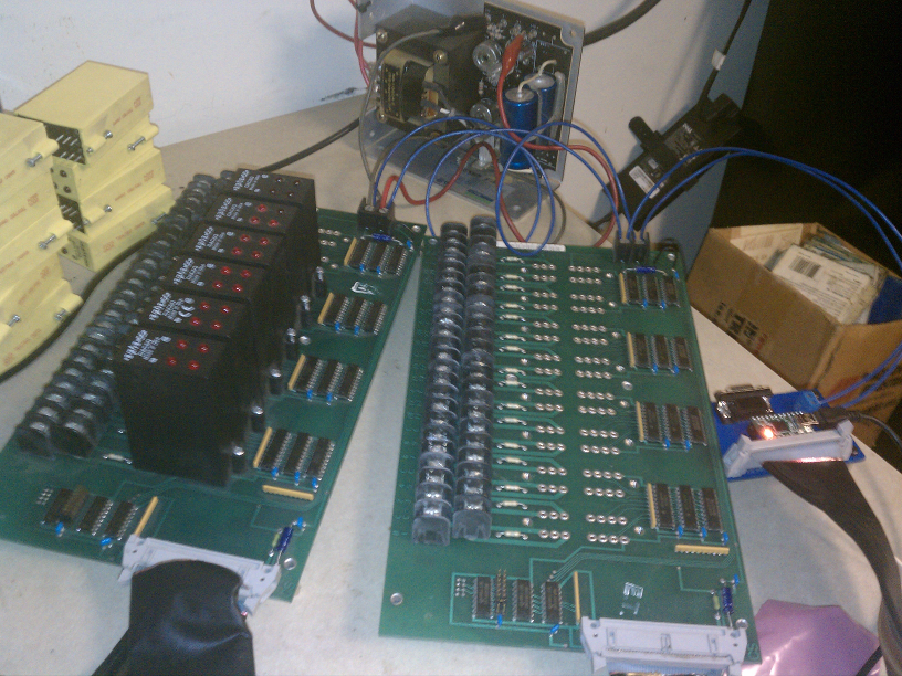
- 32 point SSR output boards
We have been aware that more and more of it’s components, especially the Electro Cam controls, were being obsoleted. Recently we were put in the position to ask ourselves what our options are when one of these proprietary controls have a permanent catastrophic failure. What we learned was that we would be given few options through the official channels. We would have to leave the machine down and idle for an undetermined amount of time while the failed component was sent to Electro Cam for assessment and possible repair. This would certainly take longer than a week, but my gut says it would be closer to a month. There are also no guarantees that the part could be repaired at all. We were quoted a price for a replacement as starting at $4500, but with no promises.
Not having a replacement for a proprietary single-sourced part on the shelf is scary. Worse is when that single source says that they really can’t help you. This is one of several (maybe many) triggers for the maintenance department that I am a part of to fly wildly into a re-engineering frenzy.
The primary design requirement of 84 output points was a stickler. Buying any PLC with that many output modules is expensive. We were able to get one design into the $3500 range, but would still need an operator interface also. The original design used a set of 3 custom-designed boards that each housed 32 outputs in the form of these Opto-22 quad SSRs. Even aside from the fact that they are already installed in the machine & thus won’t cost anything additionally, these are attractive for a number of other reasons as well: very dense form factor means the 84 points don’t take up much physical space, readily available from a lot of vendors and made by a number of large manufacturers means that they are likely to be around for a long time to come, and they have already proven their longevity by having been installed in their purpose for the last 20+ years without ever having a single failure.
We agreed that the original output boards were an elegant and optimal design, in addition to the ability to reuse these would alone save close to a thousand dollars. The problem is we had no idea how to communicate with them.
Reverse Engineering
The first step to figuring these boards out was to call Electro Cam and just ask them straight out. After a few calls it was learned that the techs at Electro Cam do not deal with these boards very often and were not at all familiar with the circuitry and control itself. I was disappointed, but completely understood..

This setback made the next step to sit down and make a schematic and try to figure out all the whats and hows. It was very fortunate that we had kept 2 spare output boards that had been removed during the first automation upgrade all those years ago. Without being able to have them sitting on my desk for about a week I would have never been able to figure out how to manipulate the outputs. Here is a rough schematic. It’s the logic portion of the circuit only. I did not include any of the supporting circuitry. The inputs of the SSRs are driven by the outputs of the buffer/driver chips and designated “OA” and their single-digit position (which is the data line that sets it’s state) as well as which SSR it is in the bank (1 or 2) and it’s relative position in the SSR.
This was my first in-depth dealing with the venerable 7400-series digital logic that I’ve heard so much about my entire adult life. To be perfectly honest it has daunted me up to this point, but I dove into the datasheets nonetheless. What I found is that this is a fairly standard old-school memory addressing architecture. Hopefully all will be made more clear in the firmware code, but first here is an overview of how these boards work for our purposes:
- The 74LS138 chip that I have designated U3 is used to address the individual boards. Setting the binary address at pins A0-2 to match the corresponding jumper position at outputs /Y0-7 allows the an enable pin of each of U1 & U2 to be brought active.
- At this point it is necessary to set the desired state of the outputs of a bank using the 8 data lines
- U1 & U2 are then used to address the 4 individual 8 output banks. A0 & A1 of U1 are set to the binary address of the desired bank and then the remaining enable pin of U1 is pulsed to give the clock pin of the bank’s flip-flop chip a rising-edge transition. This sets the flip-flop’s outputs (Q0-7) to the same state as it’s inputs. The transceiver takes these as input and in turn drives the corresponding 8 SSR positions
The Solution: Arduino industrial controller
The next task was to decide how to construct the glue logic that would tie an operator interface into direct control of these outputs. I decided on a Teensy 2.0 Arduino-compatible development board for the control as I’ve come to love these tiny CPUs through a number of projects. (such as the PacMod MIDI controller detailed elsewhere on this site) The fact that we now have control of 84 output points in a 2 inch square area using only 17 pins is astounding. That number could easily be much much higher in the same size and pin count.

We also decided on a C-More Micro 6″ color touchscreen as an operator interface. We have used a variety of the C-More sizes and models over the past 10 years and it is my unpaid opinion that you just can’t beat their price, performance, and ease of use. Seriously. In my own personal opinion in many instances it is more effective, both in cost and in efficiency, to use a $150 D05 PLC and one of the 3-inch base model displays than a number of pushbuttons. In that usage you can have, outside of the normal machine controls, machine diagnostic screens showing the real time state of every limitswitch, pushbutton, actuator, and anything else connected to the decision making process.
Due to my wanting to get this to a functional proof-of-concept stage as quickly as possible what I think is the best way to tie this all together is not the way I did it. The bottom line is that at the very beginning I was not absolutely certain that I could get it all to work together, so I needed to waste as little time as possible finding out if we needed to move on to one of our other design possibilities. In the future I may (probably will) write firmware for the Teensy that can directly communicate using the DirectNet protocol so that the C-More Micro will connect directly to the Teensy. As it stands now, I used an old D05 connected between the two. Since this tiny PLC wasn’t going to be doing anything other than acting as an intermediary for serial data from the C-More Micro to serial data to the Teensy I was able to use a D05 that had a burned output and so was removed from equipment several years ago.
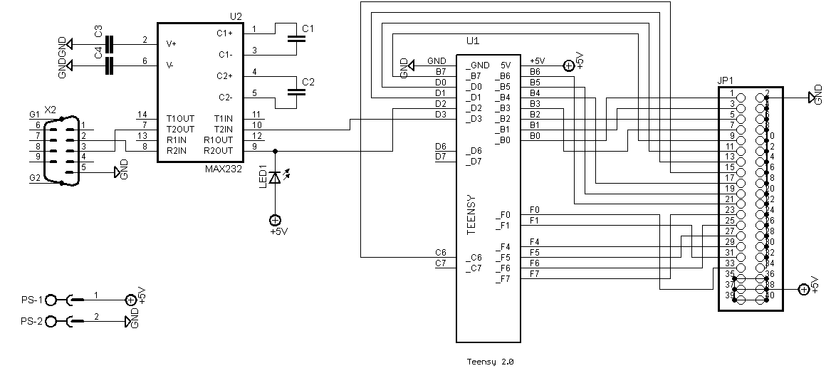
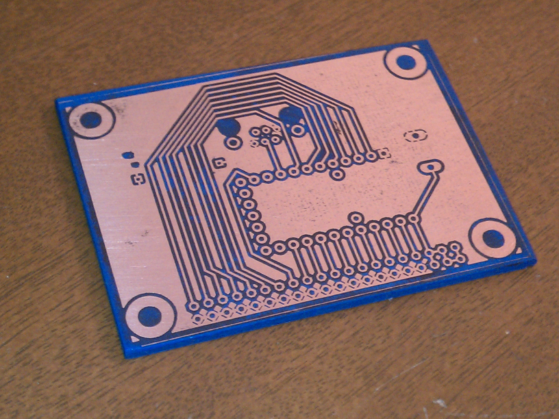
I initially breadboarded the Teensy and the 40-pin ribbon header, but once the basic control sequence and protocol were written I etched a custom adapter prototype. Several revisions were made even after this stage, each requiring a new prototype board. Once the MOTA prototype sufficiently proved itself in running production a professionally made board was ordered from ITEAD Studio
Hopefully the Teensy firmware code below is documented well enough to make it clear what is going on. The fundamental principles are that the Teensy loops through a cycle of time base duration. The 84 zones are each assigned a duty cycle percentage by the operator and will energize a heater for that percentage of the time base. There is also an overall percentage adjustment that affects all zones called comp. Comp is a percentage of each individual zones percentage. For this reason I used 3 separate arrays. One for the zone percentages, one for the calculated millis for each zone, and a third for the comp-adjusted millis for each zone. If a single zone is changed then it is only necessary for the firmware to update the 3 array positions for that specific zone. If the time base or comp are changed then the 2 resultant arrays need to be entirely recalculated.
At the beginning the time base loop all outputs are turned on. In each iteration of the loop the current elapsed time of the loop is checked against each of the comp-adjusted time calculated for each zone. Any zones that have a value less than the elapsed time are turned off. These output states have to be sent to the board for each bank through the 8 data lines.
Any time serial data is received it is processed by a handler routine. It accepts several 1, 2, and 3 byte command packets. I’ve left all of the serial debug output in since it also serves as a form of documentation for the code.
|
1 2 3 4 5 6 7 8 9 10 11 12 13 14 15 16 17 18 19 20 21 22 23 24 25 26 27 28 29 30 31 32 33 34 35 36 37 38 39 40 41 42 43 44 45 46 47 48 49 50 51 52 53 54 55 56 57 58 59 60 61 62 63 64 65 66 67 68 69 70 71 72 73 74 75 76 77 78 79 80 81 82 83 84 85 86 87 88 89 90 91 92 93 94 95 96 97 98 99 100 101 102 103 104 105 106 107 108 109 110 111 112 113 114 115 116 117 118 119 120 121 122 123 124 125 126 127 128 129 130 131 132 133 134 135 136 137 138 139 140 141 142 143 144 145 146 147 148 149 150 151 152 153 154 155 156 157 158 159 160 161 162 163 164 165 166 167 168 169 170 171 172 173 174 175 176 177 178 179 180 181 182 183 184 185 186 187 188 189 190 191 192 193 194 195 196 197 198 199 200 201 202 203 204 205 206 207 208 209 210 211 212 213 214 215 216 217 218 219 220 221 222 223 224 225 226 227 228 229 230 231 232 233 234 235 236 237 238 239 240 241 242 243 244 245 246 247 248 249 250 251 252 253 254 255 256 257 258 259 260 261 262 263 264 265 266 267 268 269 270 271 272 273 274 275 276 277 278 279 280 281 282 283 284 285 286 287 288 289 290 291 292 293 294 295 296 297 298 299 300 301 302 303 304 305 306 307 308 309 310 311 312 313 314 315 316 317 318 319 320 321 322 323 324 325 326 327 328 329 330 331 332 333 334 335 336 337 338 339 340 341 342 343 344 345 346 347 348 349 350 351 352 353 354 355 356 357 358 359 360 361 362 363 364 365 366 367 368 369 370 371 372 373 374 375 376 377 378 379 380 381 382 383 384 385 386 387 388 389 390 391 392 393 394 395 396 397 398 399 400 401 402 403 404 405 406 407 408 409 410 411 412 413 414 415 416 417 418 419 420 421 422 423 424 425 426 427 428 429 430 431 432 433 434 435 436 437 438 439 440 441 442 443 444 445 446 447 |
#include #include /* Maac Oven Teensy Adapter NAME ARD PIN CON PIN DESCRIPTION ---- ------- ------- ----------- ADDR_BOARD: D0 5 11 LSB in board address D1 4 9 2nd bit in board addr D2 3 7 MSB in board addr EN 2 5 ENABLE for U3 demux [board select][LOW ACTIVE] CLR 21 33 CLR/MR pin must be held high at all times to maintain boards' memory ADDR_BANK: D0 9 15 LSB in bank address D1 6 13 MSB in bank address E1 1 3 ENABLE for U1 demux [flip-flop select] [LOW ACTIVE] E2 0 1 ENABLE for U2 demux [buffer/driver select] [LOW ACTIVE] BANK_DATA: D0 20 17 BANK OUTPUT 1-1 D1 19 19 BANK OUTPUT 1-2 D2 18 21 BANK OUTPUT 1-3 D3 17 23 BANK OUTPUT 1-4 D4 16 25 BANK OUTPUT 2-1 D5 15 27 BANK OUTPUT 2-2 D6 14 29 BANK OUTPUT 2-3 D7 13 31 BANK OUTPUT 2-4 SERIAL PACKET: */ #define EN_DELAY 1 #define DRIVER_DELAY 1 const int PIN_LED = 11; const int PIN_CLR = 21; const int PIN_BOARD_ADDR_D0 = 5; const int PIN_BOARD_ADDR_D1 = 4; const int PIN_BOARD_ADDR_D2 = 3; const int PIN_BOARD_ADDR_EN = 2; const int PIN_BANK_ADDR_D0 = 9; const int PIN_BANK_ADDR_D1 = 6; const int PIN_BANK_ADDR_E1 = 1; // flip-flop driver const int PIN_BANK_ADDR_E2 = 0; // buffer driver driver const int PIN_BANK_DATA_0 = 20; // 13; const int PIN_BANK_DATA_1 = 19; // 14; const int PIN_BANK_DATA_2 = 18; // 15; const int PIN_BANK_DATA_3 = 17; // 16; const int PIN_BANK_DATA_4 = 16; // 17; const int PIN_BANK_DATA_5 = 15; // 18; const int PIN_BANK_DATA_6 = 14; // 19; const int PIN_BANK_DATA_7 = 13; // 20; const int EEPROM_COMP = 0; const int EEPROM_ZONES_BASE = 10; const int EEPROM_TIME = 1; const int BOARDS = 3; // # of connected boards; const int BANKS = 4; // # of banks per board const int ZONES = 84; // # of total zones elapsedMillis dutyTimer; long timeBase = 6000; // 6 second cycle int compPct = 0; int dutyCyclePct[] = { 0, 0, 0, 0, 0, 0, 0, 0, 0, 0, 0, 0, 0, 0, 0, 0, 0, 0, 0, 0, 0, 0, 0, 0, 0, 0, 0, 0, 0, 0, 0, 0, 0, 0, 0, 0, 0, 0, 0, 0, 0, 0, 0, 0, 0, 0, 0, 0, 0, 0, 0, 0, 0, 0, 0, 0, 0, 0, 0, 0, 0, 0, 0, 0, 0, 0, 0, 0, 0, 0, 0, 0, 0, 0, 0, 0, 0, 0, 0, 0, 0, 0, 0, 0, 0, 0, 0, 0, 0, 0, 0, 0, 0, 0, 0, 0 }; long dutyCycleMillis[] = { 0, 0, 0, 0, 0, 0, 0, 0, 0, 0, 0, 0, 0, 0, 0, 0, 0, 0, 0, 0, 0, 0, 0, 0, 0, 0, 0, 0, 0, 0, 0, 0, 0, 0, 0, 0, 0, 0, 0, 0, 0, 0, 0, 0, 0, 0, 0, 0, 0, 0, 0, 0, 0, 0, 0, 0, 0, 0, 0, 0, 0, 0, 0, 0, 0, 0, 0, 0, 0, 0, 0, 0, 0, 0, 0, 0, 0, 0, 0, 0, 0, 0, 0, 0, 0, 0, 0, 0, 0, 0, 0, 0, 0, 0, 0, 0 }; long dutyCompMillis[] = { 0, 0, 0, 0, 0, 0, 0, 0, 0, 0, 0, 0, 0, 0, 0, 0, 0, 0, 0, 0, 0, 0, 0, 0, 0, 0, 0, 0, 0, 0, 0, 0, 0, 0, 0, 0, 0, 0, 0, 0, 0, 0, 0, 0, 0, 0, 0, 0, 0, 0, 0, 0, 0, 0, 0, 0, 0, 0, 0, 0, 0, 0, 0, 0, 0, 0, 0, 0, 0, 0, 0, 0, 0, 0, 0, 0, 0, 0, 0, 0, 0, 0, 0, 0, 0, 0, 0, 0, 0, 0, 0, 0, 0, 0, 0, 0 }; HardwareSerial Uart = HardwareSerial(); // command types const int CMD_UPDATE_COMP = 99; // 'c' + byte[value] const int CMD_DISPLAY = 100; // 'd' const int CMD_UPDATE_ZONE = 110; // 'n' + byte[zone #] + byte[value] const int CMD_UPDATE_ZONE_VALUE = 111; // 'o' const int CMD_UPDATE_TIME = 116; // 't' + 'c' + byte[seconds] boolean waitingForCmdData = false; const int CMD_TIMEOUT_MILLIS = 100; // 0.1 sec timeout on command data elapsedMillis cmdTimer = 0; int cmdData = -1; int cmdType = -1; int cmdValue = -1; void setup() { pinMode(PIN_LED, OUTPUT); pinMode(PIN_CLR, OUTPUT); pinMode(PIN_BOARD_ADDR_D0, OUTPUT); pinMode(PIN_BOARD_ADDR_D1, OUTPUT); pinMode(PIN_BOARD_ADDR_D2, OUTPUT); pinMode(PIN_BOARD_ADDR_EN, OUTPUT); pinMode(PIN_BANK_ADDR_D0, OUTPUT); pinMode(PIN_BANK_ADDR_D1, OUTPUT); pinMode(PIN_BANK_ADDR_E1, OUTPUT); pinMode(PIN_BANK_ADDR_E2, OUTPUT); pinMode(PIN_BANK_DATA_0, OUTPUT); pinMode(PIN_BANK_DATA_1, OUTPUT); pinMode(PIN_BANK_DATA_2, OUTPUT); pinMode(PIN_BANK_DATA_3, OUTPUT); pinMode(PIN_BANK_DATA_4, OUTPUT); pinMode(PIN_BANK_DATA_5, OUTPUT); pinMode(PIN_BANK_DATA_6, OUTPUT); pinMode(PIN_BANK_DATA_7, OUTPUT); // slowish UART speed because of electrically noisy environment. Uart.begin(9600); // initialize pin states and reset dutyTimer initPins(); dutyTimer = 0; // read in stored values from EEPROM & initialize zone timing arrays int readTimeBase = EEPROM.read(EEPROM_TIME); Serial.println(String("read in time base: ") + readTimeBase); if (readTimeBase > 0 && readTimeBase < 60) { timeBase = ((long)readTimeBase * 1000); } else { timeBase = 6000; Serial.println(" invalid time base. using default"); } int readCompPct = EEPROM.read(EEPROM_COMP); Serial.println(String("read in comp: ") + readCompPct); if (readCompPct > -1 && readCompPct < 100) { compPct = readCompPct; } else { compPct = 0; Serial.println(" invalid comp %. using 0"); } for(int x = 0; x < ZONES; x++) { int readZoneValue = EEPROM.read(EEPROM_ZONES_BASE + x); Serial.println(String("read in zone[") + x + "]: " + readZoneValue); if (readZoneValue > -1 && readZoneValue < 100) { dutyCyclePct[x] = readZoneValue; } else { dutyCyclePct[x] = 0; Serial.println(" invalid zone %. using 0"); } } } void loop() { //receive & handle UART serial if (Uart.available() > 0) { while (Uart.available() > 0) { int incomingByte = Uart.read(); handleSerialData(incomingByte); } } //receive & handle USB serial if (Serial.available() > 0) { while (Serial.available() > 0) { int byteIn = Serial.read(); handleSerialData(byteIn); } } // command timer watchdog if (waitingForCmdData && cmdTimer >= CMD_TIMEOUT_MILLIS) { Serial.println("cmd data timed out"); clearCmdParam(); } if (dutyTimer >= timeBase) { dutyTimer = 0; setAllOutputs(); } else { int pos = 0; for (int board = 0; board < BOARDS; board++) { selectBoard(board); for (int bank = 0; bank < BANKS; bank++) { selectBank(bank); int bankByte = 0xFF; for (int bitOfBank = 0; bitOfBank < 8; bitOfBank++) { if (pos < ZONES && dutyTimer >= dutyCompMillis[pos]) { bitClear(bankByte, bitOfBank); } pos++; } writeBankData(bankByte); } } } } void initPins() { // CLR/MR pin must be held high throughout operation digitalWrite(PIN_CLR, HIGH); // set demux ENABLE pins high (low active) digitalWrite(PIN_BOARD_ADDR_EN, HIGH); digitalWrite(PIN_BANK_ADDR_E1, HIGH); digitalWrite(PIN_BANK_ADDR_E2, HIGH); // set board address pins low (high active) digitalWrite(PIN_BOARD_ADDR_D0, LOW); digitalWrite(PIN_BOARD_ADDR_D1, LOW); digitalWrite(PIN_BOARD_ADDR_D2, LOW); // set bank address pins low (high active) digitalWrite(PIN_BANK_ADDR_D0, LOW); digitalWrite(PIN_BANK_ADDR_D1, LOW); //set bank data pins low (high active) digitalWrite(PIN_BANK_DATA_0, LOW); digitalWrite(PIN_BANK_DATA_1, LOW); digitalWrite(PIN_BANK_DATA_2, LOW); digitalWrite(PIN_BANK_DATA_3, LOW); digitalWrite(PIN_BANK_DATA_4, LOW); digitalWrite(PIN_BANK_DATA_5, LOW); digitalWrite(PIN_BANK_DATA_6, LOW); digitalWrite(PIN_BANK_DATA_7, LOW); } void updateDutyCycle(int index, int pct) { dutyCyclePct[index] = pct; dutyCycleMillis[index] = ((long)timeBase * pct) / 100; long compMillis = (dutyCycleMillis[index] * compPct) / 100; dutyCompMillis[index] = compMillis + dutyCycleMillis[index]; Serial.println(String("update dutyCycle[") + index + "]: " + dutyCyclePct[index] + "% = " + dutyCycleMillis[index] + " + comp: " + compMillis + " = " + dutyCompMillis[index]); } boolean selectBoard(int pAddr) { boolean result = false; if (pAddr > -1 && pAddr < 3) { result = true; digitalWrite(PIN_BOARD_ADDR_D0, bitRead(pAddr, 0)); digitalWrite(PIN_BOARD_ADDR_D1, bitRead(pAddr, 1)); digitalWrite(PIN_BOARD_ADDR_D2, bitRead(pAddr, 2)); digitalWrite(PIN_BOARD_ADDR_EN, LOW); } return result; } boolean selectBank(int pBank) { boolean result = false; if (pBank >-1 && pBank < 4) { result = true; digitalWrite(PIN_BANK_ADDR_D0, bitRead(pBank, 0)); digitalWrite(PIN_BANK_ADDR_D1, bitRead(pBank, 1)); digitalWrite(PIN_BANK_ADDR_E2, HIGH); delay(EN_DELAY); } return result; } void writeBankData(int pBankData) { digitalWrite(PIN_BANK_DATA_0, bitRead(pBankData, 0)); digitalWrite(PIN_BANK_DATA_1, bitRead(pBankData, 1)); digitalWrite(PIN_BANK_DATA_2, bitRead(pBankData, 2)); digitalWrite(PIN_BANK_DATA_3, bitRead(pBankData, 3)); digitalWrite(PIN_BANK_DATA_4, bitRead(pBankData, 4)); digitalWrite(PIN_BANK_DATA_5, bitRead(pBankData, 5)); digitalWrite(PIN_BANK_DATA_6, bitRead(pBankData, 6)); digitalWrite(PIN_BANK_DATA_7, bitRead(pBankData, 7)); digitalWrite(PIN_BANK_ADDR_E1, LOW); delay(DRIVER_DELAY); digitalWrite(PIN_BANK_ADDR_E1, HIGH); //set bank data pins low (high active) digitalWrite(PIN_BANK_DATA_0, LOW); digitalWrite(PIN_BANK_DATA_1, LOW); digitalWrite(PIN_BANK_DATA_2, LOW); digitalWrite(PIN_BANK_DATA_3, LOW); digitalWrite(PIN_BANK_DATA_4, LOW); digitalWrite(PIN_BANK_DATA_5, LOW); digitalWrite(PIN_BANK_DATA_6, LOW); digitalWrite(PIN_BANK_DATA_7, LOW); } void setAllOutputs() { for (int board = 0; board < BOARDS; board++) { if (selectBoard(board)) { for (int bank = 0; bank < BANKS; bank++) { if (selectBank(bank)) { writeBankData(0xFF); } } } } } /*void resetAllOutputs() { digitalWrite(PIN_CLR, LOW); delay(EN_DELAY); digitalWrite(PIN_CLR, HIGH); }*/ void updateAllOutputs() { for(int x = 0; x < ZONES; x++) { updateDutyCycle(x, dutyCyclePct[x]); } } void clearCmdParam() { waitingForCmdData = false; cmdData = -1; cmdTimer = 0; cmdType = -1; cmdValue = -1; } void setCmdParam(int pCmdType) { waitingForCmdData = true; cmdData = -1; cmdTimer = 0; cmdType = pCmdType; cmdValue = -1; } void setCmdParam(int pCmdType, int pCmdValue) { waitingForCmdData = true; cmdData = -1; cmdTimer = 0; cmdType = pCmdType; cmdValue = pCmdValue; } void debugZoneDisplay() { Serial.println(" --- DEBUG DISPLAY ---"); Serial.println(String("time base: ") + timeBase); Serial.println(String("comp: ") + compPct); for(int x = 0; x < ZONES; x++) { Serial.println(String("dutyCycle[") + x + "]: " + dutyCyclePct[x] + "% = " + dutyCycleMillis[x] + " + comp = " + dutyCompMillis[x]); } Serial.println(" ---------------------"); } void handleSerialData(int byteIn) { Serial.print("handleSerialData: ["); Serial.print(byteIn, DEC); Serial.println("]: "); if (!waitingForCmdData && byteIn == CMD_DISPLAY) { // d - display current calculations debugZoneDisplay(); } else if (!waitingForCmdData && byteIn == CMD_UPDATE_ZONE) { // n - update single zone setCmdParam(CMD_UPDATE_ZONE); Serial.println(" wait for zone"); } else if (!waitingForCmdData && byteIn == CMD_UPDATE_COMP) { // c - update comp value setCmdParam(CMD_UPDATE_COMP); Serial.println(" wait for comp value"); } else if (waitingForCmdData && cmdTimer >= CMD_TIMEOUT_MILLIS) { Serial.println(" cmd data timed out"); clearCmdParam(); } else if (!waitingForCmdData && byteIn == CMD_UPDATE_TIME) { // t - update time value setCmdParam(CMD_UPDATE_TIME); Serial.println(" wait for time base value"); } else if (waitingForCmdData && cmdTimer < CMD_TIMEOUT_MILLIS) { switch (cmdType) { case CMD_UPDATE_COMP: if (byteIn > -1 && byteIn < 100) { Serial.print(" valid comp value rcvd: "); Serial.println(byteIn, DEC); compPct = byteIn; EEPROM.write(EEPROM_COMP, compPct); updateAllOutputs(); clearCmdParam(); } else { Serial.print(" invalid comp value rcvd: "); Serial.println(byteIn, DEC); clearCmdParam(); } break; case CMD_UPDATE_ZONE: if (byteIn > (-1) && byteIn < ZONES) { Serial.print(" valid zone rcvd: "); Serial.println(byteIn, DEC); setCmdParam(CMD_UPDATE_ZONE_VALUE, byteIn); Serial.println(" wait for zone value"); } else { Serial.print(" invalid zone rcvd: "); Serial.println(byteIn, DEC); clearCmdParam(); } break; case CMD_UPDATE_ZONE_VALUE: if (byteIn > -1 && byteIn < 100) { Serial.print(" valid zone value rcvd: "); Serial.println(byteIn, DEC); updateDutyCycle(cmdValue, byteIn); EEPROM.write(EEPROM_ZONES_BASE + cmdValue, byteIn); clearCmdParam(); } else { Serial.print(" invalid zone value rcvd: "); Serial.println(byteIn, DEC); clearCmdParam(); } break; case CMD_UPDATE_TIME: Serial.print(" time base rcvd: "); Serial.println(byteIn, DEC); if (byteIn > 0 && byteIn < 60) { timeBase = ((long)byteIn * 1000); } else { timeBase = 6000; Serial.println(" invalid time base: using default"); } EEPROM.write(EEPROM_TIME, byteIn); Serial.print(" new time base: "); Serial.println(timeBase, DEC); updateAllOutputs(); clearCmdParam(); break; } } } |
The communication protocol between the PLC and the Teensy was a source of several frustrating roadblocks. The first plan was to have the Teensy store all necessary data and the PLC would just directly pass along user activity on the operator interface. This seemed impossible because the PLC was using what DirectSoft (the PLC programming software) calls ‘non-sequence’ protocol. This means plain ASCII serial with no wrapping protocol. When using a wrapper such as MODBUS or DirectNet 2-way communications are easily implemented. Of course, if I had written the firmware to use one of these established protocols then I would be communicating directly with the operator interface and wouldn’t need the PLC at all.
When using the non-sequence protocol there is apparently no way for the PLC to receive data, only to transmit. In setting up the PLC com port for non-sequence you are required to give a memory location for data that makes it appear that this is where received data will be placed, but I was unable to get it to work and I could find exactly zero documentation for non-sequence communications. The design compromise I made was to move responsibility for storing user data up one level into the PLC.
This now makes it necessary to transmit more data from the PLC to the Teensy. Trying to accomplish this has it’s own set of problems stemming from the serial implementation in the PLC. Originally the design was to transmit small 2- and 3- byte command packets for individual zone changes and a larger 86-byte packet to transfer an entire data set at once. The PLC wasn’t having it. The scan time of the PLC processor is faster than it’s serial port transceiver so back-to-back writes to the serial port fail. It seemed obvious that I would have to format the 86 byte packet into a single write to the serial port. Luckily the DirectSoft software allows for an entire memory range to be specified and written to the port. Unfortunately when writing a range like this the PLC inexplicably writes an 0x00 char in between each legitimate byte. I could write the Teensy firmware to discard these zeroes, but it additionally has a limit of 128 characters per serial write – and it counts those zeroes as characters. Thus, the PLC considers my 86 characters as 172 and refuses to write it to the port correctly.
The PLC strangely does not write a zero after a single byte write, so I tried doing a single write as a huge chunk of single byte calls, but again I was thwarted. This time by the text-size limit in the IDE.
This forced me to write a hugely complicated and very efficient command queuing system to manage and send the 86 individual 2- and 3- byte packets. This was too efficient and would overflow the PLC serial transmit buffer in around 70 command messages.
I ended up using a very slow packet queuing process that takes between 15 and 60 seconds to transfer all of the data set varying with how sleepy the PLC is. Depending on how much success I have writing the DirectNet protocol into the firmware I may eventually re-write the original fast block transmission into 3 smaller block commands.