Teensy PSX MACH3 Pendant build
 The Premise:
I had been using a simple USB number pad as a pendant controller for my CNC router. This was somewhat cumbersome. A PSX controller that I got at a yard sale to make a MIDI controller for my son seemed like a good choice for an upgrade. I ended up making him the PACMOD MIDI DJ Controller instead so this had just been staring at me for the last 7 or 8 years. It can actually be made into any kind of USB controller you want. Once built the code can be updated without opening it again.
Honestly , other than the cool form factor there is no real reason to convert a PSX controller to be a CNC pendant control. In fact the Teensy can handle a lot more directly wired buttons than are on the controller. There are also a number of methods to multiplex even more inputs if necessary. Really, making a custom pendant would make much more sense. I believe it would be fairly trivial to make one of the USB PSX controller clones work as well (and I plan to try that soon.)
So now that we’re on the same page and understand that this is the wrong way to go about this let’s get started.
For the brains I used a Teensy 2.0 from PJRC.com – I was going to use a Digispark, but the Teensy will do USB HID easily and flawlessly. I have read is not the case with the Digispark. Comparing them side-by-side they are surprisingly almost exactly the same size as well. The Teensy just feels way bigger for some reason.
The basic Arduino and Teensy set up are beyond the scope of this write-up, but if you want to use a Teensy for the first time go to PJRC.com and get the drivers and libraries and such. They have a good tutorial for getting started with Teensy. Other newer Arduinos and compatibles may have the native USB support required for this particular project and be small enough to physically fit but I have never used any so cannot speak to that.
 The Wiring:

I opened the controller and cut the PSX cable off. A few inches of wiring were left to enable soldering to the Teensy. The internal wiring connector for my controller, as seen in the picture and included in the code below, was as follows
| PSX wire | function | Teensy connection |
|---|---|---|
| GRN | unused | n.c. |
| BRN | data | pin 8 |
| BLK | 0vdc | ground pin |
| RED | 5vdc | +5vdc pin |
| YEL | attention | pin 7 |
| ORG | command | pin 9 |
| BLU | clock | pin 10 |
If you decide to make this controller get yourself the longest USB 5-pin Mini-B cable you can. Wind it into the compartment in the same way as the original cable. I had to remove the rubber from around the mini side to get it to fit.
The Firmware:
The PSX controller actually implements a serial interface to communicate. There is an existing PSX library to handle communications. However I felt that adding signal edge detection would be a major improvement for the intended application. I adapted functions from the Bounce library and added them into the PSX library. I did a little housekeeping as well.
You can download my version here: PSX2.zip
The reason for using edge detection is that the model I am using for this controller is a standard keyboard. It is sending the same keystrokes to Mach3 that would be used from any other keyboard. The computer that is running Mach 3 cannot tell that it is receiving data from anything other than a standard USB keyboard. Keyboards only send data for keys on state changes. Any key for which an ON state command has been sent will be considered being held down until the corresponding OFF state command is sent. This dictates how we handle the PSX controller data.
You can see in the code below that aside from the initiating code there is a single block for each button on the PSX controller. Each block has a rising edge handler for the button that sends key press packets for all the elements of the desired keystroke to MACH3. Each block also has a falling edge handler that sends key release packets. It’s really that easy.
Download the sketch code here: Mach3_Pendant_001.ino
An error has occurred. Please try again later. |
 The Usage:

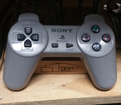
I have mapped the controls into what I feel is a logical and intuitive arrangement.
On the left side the arrow buttons are the X/Y axis motor controls, L1/L2 are the Z axis, and R1/R2 are the A axis that I plan to add in the future.
On the right side:
- triangle is “rewind”. (It looks a little like the rewind transport icon.)
- square is Auto Z. (It can be interpreted to be a gauge block: check out my write-up on making a cheap one.)
- circle is unused
- X is stop.
In the center “start” is start and “select” is pause.
Of course the arrangements and functions are easily editable.
Feel free to contact me with any questions and if you build one be sure to tag _ophelion on instagram!